Designing Complex Parts for Space and Aerospace Applications
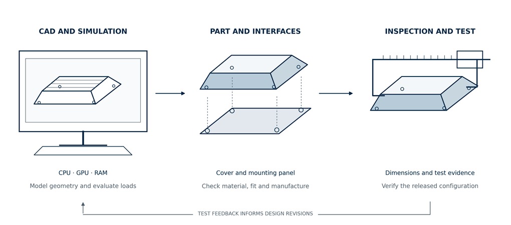
Complex aerospace part design connects a physical component with the digital tools used to develop it. A cover, bracket, or panel must fit its assembly, survive its operating environment, and be manufactured with properties that engineers can verify. Meanwhile, the design team needs a workstation that can handle CAD models and the analyses used to assess them.
Define the job before designing the part
Aerospace covers very different applications. An aircraft cabin panel, a ground equipment cover, and an external spacecraft bracket do not face the same conditions. Their requirements should reflect where they operate, what they support, how long they must last, and what happens if they fail. Treating every component as generic “aerospace hardware” can lead to unnecessary expense or inadequate testing.
Begin with the interfaces. Establish mounting locations, available space, allowable movement, and the loads transferred through adjacent components. Include access for assembly tools, wiring, and inspection. A bracket that meets its strength target can still be unusable if a technician cannot reach a fastener or if thermal expansion closes a necessary clearance.
Record each requirement in a form that can be checked. “Lightweight and durable” provides little direction; a defined mass allocation, operating temperature range, and service life create measurable targets. Agree on the applicable customer requirements and approval route before detailed design. Aircraft certification and spacecraft qualification follow different frameworks, so no single approval automatically covers every aerospace application.
Choose materials for the complete operating environment
Material selection involves trade-offs between stiffness, strength, density, temperature response, corrosion, and manufacturability. Aluminum alloys may suit machined housings and structures; titanium can be useful where strength, temperature, and corrosion requirements justify its cost. Composites and engineering polymers offer other options, but their suitability depends on the specific grade, reinforcement, geometry, and service conditions.
Compare properties at the conditions the part will experience. Room temperature tensile strength alone does not establish performance under repeated loading or prolonged heat. For a polymer cover, creep can change a fastening interface over time. For a composite panel, fiber direction and the arrangement of layers affect stiffness and strength. Material data should match the manufacturing route closely enough to support the analysis.
Vacuum exposure and contamination
Vacuum introduces a concern that is easy to miss when selecting plastics, adhesives, coatings, and potting compounds: outgassing. Released substances may contaminate nearby surfaces, including sensitive optical equipment. NASA’s outgassing database provides material test data based on ASTM E595, including total mass loss and collected volatile condensable material. It is a useful starting point for assessing low outgassing performance.
A database result must still be interpreted in context. Check the exact material and the preparation conditions, then compare the evidence with the project’s requirements. Outgassing data does not, by itself, establish radiation resistance, structural capability, or suitability for every spacecraft location. Keep the material, finish, adhesive, and cleaning process within the same review because the finished assembly is what enters service.
Select a manufacturing process that suits the geometry
The manufacturing route influences what a design can achieve and how its quality can be demonstrated. Machining offers controlled metal features and accessible inspection surfaces. Composite layup supports lightweight shells and panels, although tooling, fiber placement, and curing need control. Additive manufacturing can produce internal passages and integrated features that would be difficult to machine.
Compare the full production route rather than the initial forming or printing operation. Include finishing, trimming, heat treatment where applicable, inspection, assembly, and likely rework. A component with fewer individual parts may reduce assembly work but become harder to inspect or replace. A simpler geometry may therefore deliver better overall value even if its modeled mass is slightly higher.
Where thermoforming fits?
For contoured plastic covers, guards, liners, and panels, engineers can review RapidMade’s thermoforming solutions to assess a route from design review and tooling through forming, trimming, and inspection. The company describes engineering review, mold and fixture design, CNC trimming, first article inspection reports, and certificates of conformance among its services. These capabilities give a project team concrete subjects to discuss before requesting a quote; the selected material and finished part still need to meet the application’s requirements.
Thermoforming heats a plastic sheet and shapes it over or into tooling. Vacuum forming is one method within that process family: air is removed from between the sheet and tool, allowing atmospheric pressure to push the softened sheet against the mold. After cooling, the formed part is removed and trimmed. Figure 2 shows the principle using a simplified cover cross-section.
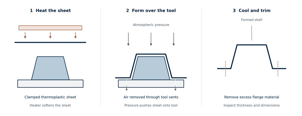
A supplier offering custom vacuum forming services should assess the geometry before the design is released. Draft angles help a formed part separate from its tool, while corner geometry and draw depth influence how the sheet stretches. The starting sheet thickness should not be assumed to remain uniform throughout the finished component. Local thinning can affect stiffness, fastening details, and dimensional consistency.
For larger covers and panels, heavy-gauge industrial thermoforming may be a suitable route. However, a thicker starting sheet does not establish flight suitability. The final material distribution, trimmed edges, mounting features, and environmental performance still need evaluation. Thermoforming should be selected for a defined application rather than presented as an interchangeable substitute for machined structural metal parts.
Additive manufacturing and inspection
Additive manufacturing can support compact passages, consolidated assemblies, and geometries shaped around load paths. Those advantages introduce questions about build orientation, surface condition, internal access, and the removal of residual material. Engineers should decide how critical features will be inspected before committing to a geometry that hides them.
NASA’s explanation of additive manufacturing requirements for spaceflight describes controls covering material processes, equipment, personnel, and part production. Its discussion includes build orientation, witness testing, and inspection limitations. The practical lesson is that qualification concerns the controlled production method as well as the finished shape. A successful print alone is insufficient evidence of repeatable flight hardware quality.
Build CAD models that support engineering decisions
A useful CAD model describes interfaces, tolerances, and manufacturing intent, not only the outside shape. Identify the surfaces that locate the part in its assembly and distinguish functional dimensions from cosmetic details. This helps prevent unnecessary precision from increasing cost while a genuinely critical interface receives too little attention.
Tolerance analysis should consider how several parts fit together. Individually acceptable dimensions can combine into an unacceptable assembly gap or interference. Include expected thermal movement where it matters, and review how a plastic cover attaches to a metal structure. Different expansion behavior can affect clearances and fastener loading even when the initial assembly fits correctly.
Keep the released design connected to the correct material specification, drawing revision, and analysis model. When a hole moves or a wall becomes thinner, the previous simulation may no longer represent the part being manufactured. Consistent revision control makes it possible to identify which evidence supports each configuration and which checks must be repeated after a change.
Match CPU and GPU selection to the engineering workload
Workstation planning belongs alongside software planning because different engineering tasks stress different components. Editing a parametric model, rotating a large assembly, solving a structural analysis, and producing a rendered image are separate workloads. Buying the most expensive graphics card does not guarantee that all four will become faster.
Start by identifying the software version, typical model size, solver type, and available licenses. Then measure representative tasks on an existing or trial system. Record completion times, peak memory use, and whether the task actually uses the CPU or GPU heavily. These observations provide a stronger purchasing basis than a single overall performance score.
Choose a CPU around the tasks you run
Some CAD operations depend heavily on performance from a limited number of processor cores, while supported simulation and rendering tasks can use more parallel processing. The useful balance depends on the application and operation. Core count alone therefore cannot predict whether a workstation will feel responsive during modeling or finish a particular analysis sooner.
CPU benchmarks provide a starting point for comparing processors. Use broad comparisons to develop a shortlist, then examine results from the CAD or analysis software you intend to use. Gaming rankings do not establish finite element solver performance, and a general multicore score cannot reveal every limitation in a specific engineering workflow.
Check whether additional cores require a different software license and whether your typical models can use them efficiently. Cooling also matters during sustained work: a short benchmark may not represent performance during a long solve. Choose the processor, motherboard, memory configuration, and cooling system as a supported combination with enough capacity for the planned workload.
Select a GPU for the viewport and supported calculations
The GPU helps display and manipulate three-dimensional models, but graphics display and numerical computation are different responsibilities. A solver only benefits from GPU acceleration when the software supports the relevant hardware and calculation method. Support can vary between products and versions, so confirm it before assigning a large share of the budget to a graphics upgrade.
The GPU benchmarks compare general graphics performance. For aerospace CAD, follow that comparison with checks for application support, driver certification, and graphics memory needs. A card that performs well in games is not automatically the best supported choice for a professional CAD installation.
For example, the official SOLIDWORKS system requirements list 16 GB of RAM, recommend 32 GB, direct users to certified graphics cards and drivers, and recommend SSD storage. These requirements provide an application baseline, not a capacity guarantee for every assembly or simulation. Check the guidance for your installed release and allow for the size of your own projects.
Use a bottleneck estimate as an initial comparison
Before choosing a CPU and GPU combination, a bottleneck calculator can provide an initial configuration estimate and help frame questions about component balance. Treat the result as a planning aid. It cannot certify CAD compatibility, determine engineering accuracy, or predict the runtime of a particular simulation. Software requirements and representative application tests should determine the final choice.
System memory and storage deserve their own assessment. An analysis that exceeds available RAM may slow substantially as data moves to storage. GPU memory can separately limit a supported GPU workload. Measure both where relevant, and keep enough storage for project files, temporary solver data, and results. An SSD supports file handling, but it does not replace adequate RAM or a reliable backup process.
Make simulation credible before making it faster
Simulation can help compare designs before manufacturing, provided the model represents the physical problem. Define loads, constraints, contacts, and material behavior deliberately. A part fixed too rigidly in the model can appear stiffer than its actual installation. Likewise, applying a load in the wrong direction can produce a convincing image that answers the wrong question.
Check sensitivity to mesh refinement and to uncertain assumptions. If a small change in the mesh or support condition causes a large change in the result that governs the decision, investigate before accepting the design. Review deformation and reaction forces alongside stress results. A colorful stress plot becomes useful only when the setup and interpretation are defensible.
Thermal analysis may also need to feed into structural analysis because expansion changes clearances and stresses. Vibration behavior, repeated loading, and local stress concentrations can require separate attention. Choose analyses according to the failure mechanisms that matter to the component rather than running a standard collection of studies without a clear decision in mind.
Generative design and topology optimization can suggest alternative material layouts, but their outputs still need engineering review. Add manufacturing constraints and preserve necessary interfaces. Then check the resulting geometry for accessibility, minimum features, inspection feasibility, and the same service conditions applied to the original design. Faster computation helps teams explore options; it does not remove those obligations.
Plan prototypes and testing around unanswered questions
A prototype should have a stated purpose. A fit model can reveal an inaccessible screw or a cable interference without proving structural capability. A material coupon may help investigate process consistency without representing the complete assembly. Define what each article is intended to demonstrate so that early success is not mistaken for complete qualification.
Distinguish design qualification from acceptance of production hardware. Qualification addresses whether the design can meet its specified requirements under the agreed program approach. Acceptance checks focus on whether delivered articles conform and are free from unacceptable workmanship defects. The exact methods and test levels depend on the project; they should be established by the responsible engineering and quality teams.
When physical results disagree with a simulation, examine the test setup as well as the model. Fixture flexibility, material variation, measurement uncertainty, and boundary conditions may explain the difference. Update the model using justified evidence and document the changes. Simply adjusting inputs until a preferred answer appears would weaken the value of the analysis.
Choose suppliers who can support repeatable production
Evaluate suppliers on the evidence they can provide for the intended part. Relevant OEM plastic component manufacturing experience should include discussions about materials, tooling, trimming, dimensional control, and records. Ask which operations are performed internally, which are subcontracted, and how changes to materials or processes are reviewed.
Access to in-house plastic tooling and prototyping can make design iterations easier to coordinate. Its value depends on whether lessons from prototypes are transferred into controlled production tooling and inspection methods. Confirm ownership of tooling, revision identification, maintenance responsibilities, and the method used to approve the first production article before placing a repeat order.
For a supplier review, send the CAD model with a controlled drawing, expected order quantity, preferred material grade, finish requirements, and the dimensions that govern assembly. Ask the supplier to identify forming limits, anticipated thickness variation, and how trimmed features will be measured. Agree on what documentation accompanies delivery. A certificate of conformance should refer to the agreed specifications; it should not be interpreted as blanket approval for aircraft or spacecraft use.
Compare total cost across the expected quantity and service life. A cheaper component may create additional assembly work, inspection expense, or replacement difficulties. Conversely, an elaborate manufacturing route may add little value to a simple cover. Include spare parts, supplier continuity, and the practical consequences of a rejected batch when judging the commercial proposal.
Conclusion
Designing complex parts for space and aerospace applications works best when manufacturing, analysis, and verification inform one another from the start. Materials and processes must suit the component’s function, while prototypes and tests must address specific uncertainties. A suitable CPU, GPU, memory capacity, and storage setup helps engineers evaluate designs efficiently, but the evidence still comes from controlled models, documented production, and appropriate testing. Connecting those decisions produces a clearer route from an initial concept to a component that meets its intended requirements.