
How Temperature-Controlled Switching Works in Electronics and PC Cooling
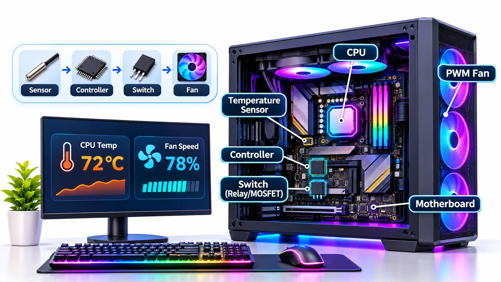
A gaming PC can run quietly while browsing the internet but generate considerably more heat when running demanding games or rendering videos. The same problem occurs in power supplies, circuit boards, and industrial electronics, where excessive temperatures can reduce efficiency, accelerate component degradation, and eventually cause hardware failures.
Cooling fans and heatsinks help remove this heat, but running cooling equipment at maximum capacity all the time is not always necessary. A better approach is to make cooling respond to temperature changes. This is where temperature-controlled switching becomes useful, allowing electronic systems to manage heat automatically without constant manual adjustments.
What Is Temperature-Controlled Switching and How Does It Work?
Temperature-controlled switching monitors temperature through a sensor and automatically turns an electrical device on or off, or adjusts its operation, when a programmed threshold is reached. A thermistor, semiconductor sensor, or thermal switch detects temperature changes, while a controller or switching mechanism determines the appropriate response. For example, a cooling fan can activate when a circuit reaches 140°F (60°C) and turn off when the temperature falls to approximately 130°F (54°C). The difference between these thresholds is called hysteresis, which prevents the fan from constantly switching as the temperature fluctuates. Depending on the circuit design, temperature-controlled switching can operate through a mechanical thermal switch, an electronic controller, or software-based temperature management.
Not every system needs a microcontroller or a complex circuit. A basic bimetallic thermostat can physically open or close electrical contacts at a specified temperature. More advanced designs can measure several temperature points, adjust fan speed, and initiate protective shutdowns if cooling becomes insufficient.
The right method depends on whether the application needs simple on/off switching, precise temperature control, or extra protection against overheating.
Temperature Sensors and Control Logic
The accuracy of a temperature-controlled system depends on its sensor. Different sensing technologies respond differently to heat, so choosing an appropriate sensor involves considering the expected temperature range, response time, accuracy, and operating conditions.
NTC (Negative Temperature Coefficient) thermistors are common in electronic circuits because their resistance decreases as temperature increases. PTC thermistors behave differently, with resistance increasing as temperature rises. Some PTC devices are designed for overcurrent protection rather than precise temperature measurement.
Semiconductor temperature sensors can provide analog voltage outputs or digital readings through interfaces such as I²C and SMBus. Thermocouples are useful for measuring high temperatures, although accurate readings require cold-junction compensation. Industrial systems may also use resistance temperature detectors (RTDs), including Pt100 and Pt1000 sensors, when measurement stability and a broad temperature range are important.
An often-overlooked issue with thermistors is that their resistance-to-temperature relationship is nonlinear. A controller must convert resistance into a meaningful temperature value using calibration data, a beta parameter, or the Steinhart–Hart equation. As explained in Analog Devices’ thermistor measurement guide, measurement accuracy also depends on the sensing circuit, reference components, and signal conversion.
Why Sensor Placement and Calibration Matter
Even an accurate temperature sensor can provide misleading information when installed in the wrong location. For example, a sensor measuring the air inside a PC case may report 40°C while a processor or voltage regulator operates at a much higher temperature.
This happens because the internal semiconductor junction, heatsink, circuit board, and surrounding air do not share the same temperature. Heat takes time to travel between these locations, creating thermal lag. A controller monitoring case air may therefore respond later than one reading the temperature directly from a processor’s internal sensor.
When designing a circuit, I would place the sensor close to the component whose temperature matters, rather than simply choosing the easiest mounting location. For a power transistor, this might involve monitoring its heatsink or nearby PCB area while accounting for the temperature difference between the sensor and the semiconductor junction.
Thermistors also require careful measurement and current selection. Passing too much current through the sensing element can cause self-heating, making its reported temperature slightly higher than the surrounding environment. Calibration, proper mounting, and suitable measurement circuitry help reduce these errors.
How Hysteresis Prevents Unnecessary Switching
Temperature does not remain perfectly stable around a control threshold. Electrical noise, airflow changes, and variations in processor workloads can cause readings to move slightly above and below a selected value.
Consider a cooling controller programmed to activate a fan at exactly 60°C and deactivate it at the same temperature. If the measurement fluctuates between 59.9°C and 60.1°C, the fan could repeatedly turn on and off. This behavior is called switching chatter.
Hysteresis solves the problem by establishing separate activation and deactivation thresholds. Analog comparators can implement this behavior through positive feedback, while digital controllers can use programmed limits. Texas Instruments’ comparator hysteresis reference design demonstrates how separate voltage thresholds reduce unwanted output transitions.
Some controllers also use temperature averaging, minimum operating times, or switching delays. These techniques serve different purposes: hysteresis prevents repeated threshold crossings, while filtering and delays help manage short temperature spikes and the slower thermal response of cooling equipment.
How Temperature Controllers Switch Electrical Loads
Once the controller determines that cooling is required, it needs a switching device capable of operating the connected electrical load. The correct component depends on the supply voltage, current demand, switching frequency, and electrical isolation requirements.
For applications involving separate control and load circuits, electrical relays for temperature-controlled switching applications are one option. An electromechanical relay energizes a coil to open or close electrical contacts. This allows a low-power temperature controller to operate an appropriately rated fan, heater, pump, or alarm circuit while maintaining galvanic isolation between the control and switched circuits.
Solid-state relays (SSRs) perform a similar function electronically without mechanical contacts. They avoid contact wear and can be useful where frequent switching is required. However, they introduce other considerations, including leakage current, heat dissipation, and compatibility with AC or DC loads. An AC SSR designed around a triac, for example, is not automatically suitable for switching a DC fan.
Transistors and MOSFETs offer another method for controlling low-voltage DC equipment. A logic-level N-channel MOSFET can switch a 12V cooling fan using a low-power controller output, provided the MOSFET is appropriately rated and driven. MOSFETs can also support high-frequency switching, making them suitable for certain motor-control designs.
Electrical Ratings and Protection Requirements
A component’s switching function does not guarantee that it can safely handle every electrical load. Relay contacts must be rated for the actual voltage, current, and load type. Motors can draw a higher current during startup than during normal operation, so a design based only on running current may be inadequate.
Relay coils and other inductive loads can also generate voltage transients when switched off. A flyback diode or another suitable suppression network may be required to protect the driving electronics. MOSFET-based circuits need proper gate drive, thermal management, and protection appropriate to the connected load.
For a PC cooling project, I would check the motherboard fan-header current rating before attaching several fans through a splitter. If their combined current or startup demand exceeds the header’s rating, a separately powered fan hub is a safer option, provided it is compatible with the motherboard and connected fans.
Applying Temperature-Controlled Switching to PC Cooling
Modern computers use temperature monitoring to manage CPU cooling, graphics cards, motherboard components, and other heat-generating hardware. Internal sensors supply temperature data to firmware or embedded controllers, which adjust cooling behavior according to predefined settings.
Unlike a basic thermostat that only turns a fan on or off, PC cooling often uses variable-speed control. Four-pin PWM fans typically receive a constant power supply while a separate Pulse Width Modulation signal controls their operating speed. Three-pin fans generally use DC voltage regulation when the motherboard supports it.
Most motherboards allow users to configure fan behavior through BIOS or UEFI settings. A fan curve determines how the requested fan speed changes with temperature, allowing quieter operation at lower thermal loads and stronger cooling when temperatures increase.
One detail worth understanding is that a fan curve cannot compensate for an inadequate heatsink, poor thermal contact, or obstructed airflow. Automatic speed control manages available cooling capacity; it cannot create additional cooling capacity beyond what the hardware can deliver.
How PWM Signals and Fan Speed Feedback Work
A conventional four-pin PC PWM fan uses connections for ground, power, tachometer feedback, and PWM control. In a typical 12V PC fan, the motor electronics receive 12V power while the fourth pin carries a separate control signal.
The Intel four-wire PWM specification uses a target control frequency of 25 kHz, with an accepted operating range of 21–28 kHz. The signal’s duty cycle determines the requested speed, although the relationship between duty cycle and actual RPM depends on the fan design.
The tachometer connection provides another useful function: it allows the motherboard or controller to monitor fan rotation. Many fans produce two tachometer pulses per revolution. For those models, the fan speed can be calculated using:
RPM = (Tachometer frequency × 60) ÷ 2
For example, a tachometer signal measuring 80 Hz corresponds to 2,400 RPM when the fan produces two pulses per revolution. The pulse count must be verified because it is not universal across all motors.
These electrical details matter when designing custom fan controllers with an Arduino, ESP32, or other microcontroller. The Noctua guide to PWM setup and RPM monitoring explains signal requirements, tachometer monitoring, and the importance of using the correct control connection.
Creating a Fan Curve for Consistent Cooling
A common mistake when configuring PC cooling is focusing only on the lowest possible fan noise. A fan curve should account for idle temperatures, sustained workloads, and the maximum operating temperatures permitted by the hardware manufacturer.
For a practical starting point, a user might configure moderate fan speeds during light workloads, increase airflow progressively as the processor heats up, and use higher speeds under sustained CPU or GPU load. Exact temperature points and percentages should be chosen for the specific processor, cooler, and case rather than copied from another system.
I would also check whether the fan can reliably start at the selected minimum speed. Some fans continue spinning at a duty cycle that is too low to start them from a complete stop. A motherboard’s fan calibration feature can help identify the minimum stable operating range.
Fan response delays are useful for another reason. A processor can briefly increase temperature when opening a demanding application, even though the heatsink temperature has barely changed. A short, configurable response delay can prevent sudden fan-speed jumps without compromising sustained cooling.
Building a Simple Temperature-Controlled 12V Fan Circuit
A basic temperature-controlled fan is a useful way to understand how these components work together. The circuit can consist of an NTC thermistor, a fixed resistor, a comparator, a switching transistor or MOSFET, and a 12V DC fan.
The thermistor and resistor form a voltage divider that produces a temperature-dependent voltage. The comparator checks that voltage against a reference and changes its output when the selected threshold is reached. A properly driven MOSFET then switches the fan’s power supply according to the controller’s output.
A comparator with positive feedback can establish separate switching thresholds without requiring a microcontroller. Alternatively, a microcontroller with an analog-to-digital converter can read the thermistor voltage, calculate temperature, and control the fan using software.
In either arrangement, the fan should be powered from a supply that can handle its electrical requirements. The controller output must not be expected to carry motor current directly unless its specifications explicitly allow it. The circuit should also include appropriate wiring protection and a defined startup state.
This approach is suitable for low-voltage electronics projects, small ventilated enclosures, and custom cooling experiments. Mains-powered equipment requires additional isolation, protective measures, and properly rated components rather than a direct extension of the same low-voltage circuit.
Why Cooling Systems Need Fail-Safe Protection
Automatic temperature control improves thermal management, but a cooling system must also account for sensor failures, stalled fans, and unexpected increases in heat generation.
A disconnected thermistor, for example, can appear as an extremely high or low resistance depending on the circuit configuration. Without appropriate fault detection, the controller could interpret the failure as a safe temperature and leave the cooling fan disabled.
A safer design defines what happens when a sensor reading becomes invalid. Depending on the application, the controller might command maximum cooling, issue a warning, reduce equipment power, or shut down the protected circuit.
Fan-speed feedback can help detect another common failure. If the controller requests high fan speed but the tachometer reports no rotation, a fan fault may be present. This is more informative than assuming that a powered fan is operating correctly.
Modern processors also provide thermal protection mechanisms, including throttling and emergency shutdown behavior. These mechanisms protect the hardware when cooling becomes inadequate, but they should not be treated as substitutes for a properly installed and functioning cooling system.
For equipment with significant safety consequences, an independent thermal cutoff may be necessary. Such protection should remain effective even if the main controller or its software fails.
How to Test a Temperature-Controlled Cooling System
A cooling system should be tested under changing thermal conditions rather than judged only by its idle temperature. A computer that appears stable during light use may behave differently during a long gaming session, compilation task, or sustained rendering workload.
For PC cooling, I would begin by checking temperature readings and fan RPM at idle. I would then run a controlled workload within the manufacturer’s operating limits and observe whether fan speed rises as expected. After removing the workload, I would check whether the fan slows smoothly instead of repeatedly jumping between speeds.
For a custom electronic controller, testing should also cover the switching thresholds, sensor accuracy, and output response. Measuring the activation and deactivation temperatures separately can reveal an incorrectly configured hysteresis range.
It is also worth verifying the system’s response to an invalid sensor reading or missing RPM signal through supported firmware diagnostics or a controlled bench-test setup. Disconnecting a critical CPU cooler during a running workload is not an appropriate way to perform this check.
These tests help reveal problems that component specifications alone cannot show, including poor sensor placement, unstable fan startup, electrical interference, and delayed cooling response.
Conclusion
Temperature-controlled switching makes electronic cooling more efficient by connecting temperature measurements to an appropriate electrical response. Its operation depends on three fundamental elements: a reliable sensor, suitable control logic, and a switching device capable of handling the intended load.
For simple electronics, an NTC thermistor and comparator may be sufficient to control a cooling fan. More advanced systems use microcontrollers, PWM signals, tachometer feedback, and multiple temperature sensors to achieve better regulation and fault detection.
In PC cooling, the most useful approach is not simply to run fans faster. It is to understand what temperature is being measured, how the fan responds, and whether the cooling hardware can manage sustained heat generation.
A well-designed system combines accurate measurements, stable switching thresholds, suitable electrical ratings, and protective behavior when something goes wrong. Those considerations matter just as much as fan speed when building reliable temperature-controlled electronics.